How to SDN 2/2 (Breakout)
Do you want to network several projects within one account or accounts among each other? In this tutorial, we will show you how this is possible with the Partner Panel function SDN. The following steps describe an example of how servers in different projects can be securely linked (via a breakout) to a firewall (this is useful, for example, if you want to administer multiple accounts using one firewall).
If you want to learn how to connect projects first, use the predecessor of this tutorial: How to SDN 1/2 (Virtual Switch)
What is the difference between a Breakout and a Virtual Switch?
A virtual switch connects several projects of one/several accounts within one location as a layer 2 network. All connected servers are then located in the same network segment across projects. The combination of Breakout and Virtual Switch automatically creates VLANs and displays the respective ID in the context menu of the SDN/PartnerPanel.
The division into VLANs can help you e.g. to centrally manage multiple accounts with one firewall. Furthermore, there is a limit of 8 networks per server – by using our SDN you can use up to 4096 VLANs per breakout.
Prerequisites
To use SDN, you need a Partner Panel or access to it. SDN is not available at my.gridscale.io. If you don’t have a partner panel yet you can get more information here.
Instruction
Step 1
We start with the basic configuration in the Partner Panel. To do this, open the menu item “SDN” and make sure that the location is selected in which your firewall is also located. (Note: We do not currently offer inter-data center interconnect. Projects can only be interconnected within a site).
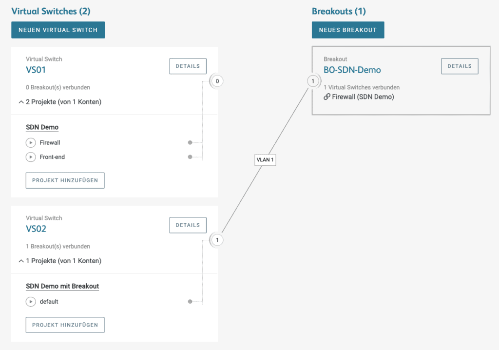
First, create a breakout (we call ours “BO-SDN-Demo”) and select the project where your firewall resides.
Next, you create a new Virtual Switch (here “VS02”). Here you select the project in which the server is located that you want to connect to the firewall.
You can choose a project in the account of the firewall or use another account. We have created a new account (named “SDN Demo with Breakout”).
To complete the basic configuration, the Virtual Switch we just created is connected to the breakout. A VLAN with the VLAN ID “1” is created.
Step 2
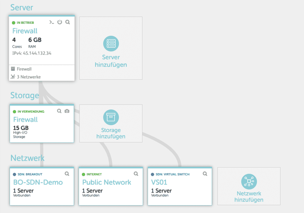
In the second step we switch (e.g. using the jump-in icon) to the cloud panel where your firewall is located. There you connect the firewall server to the breakout. The firewall should now be connected to the Internet, the first virtual switch, and the breakout.
Now turn on the firewall and access the firewall web interface.
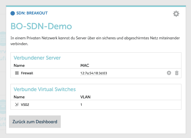
Note: If you are unsure which Mac address to define in the firewall, you can find it in the breakout detail within the cloud panel.
Step 3
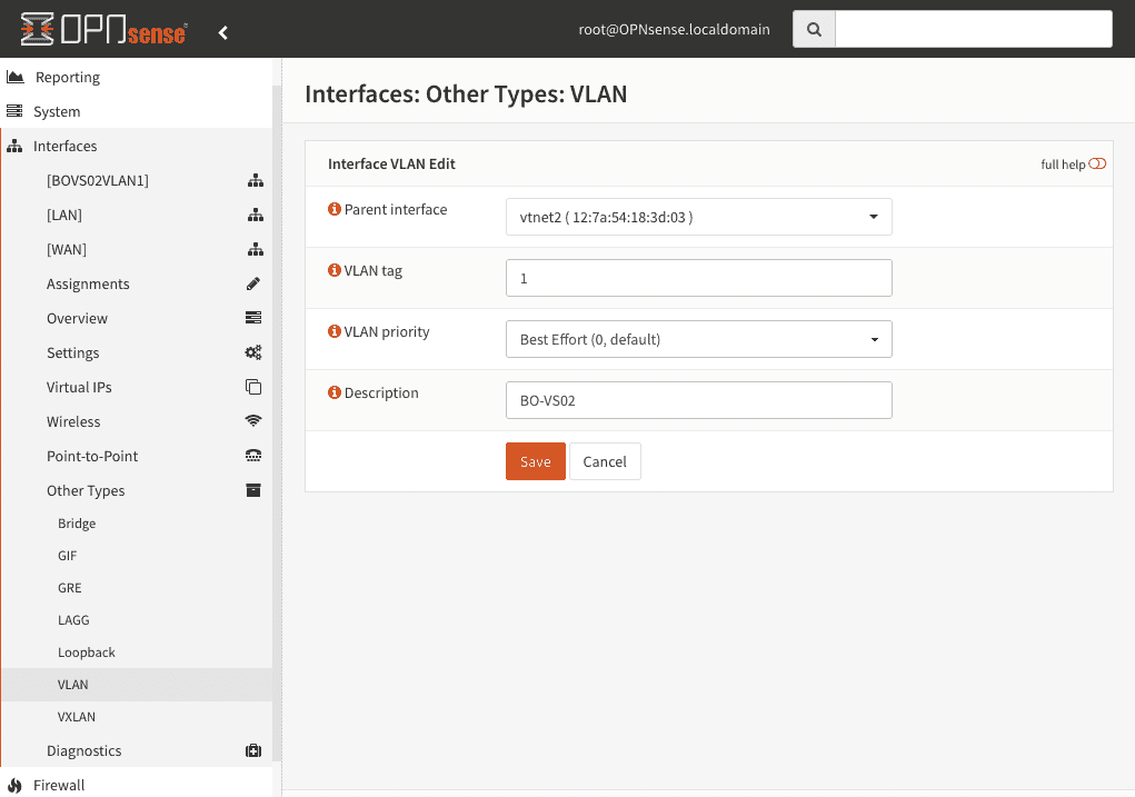
After you have logged in, we can configure the firewall with the interface and define VLAN on the correct interface of the firewall. To do this, we follow the following three simple steps:
1. the VLAN is configured on the interface.
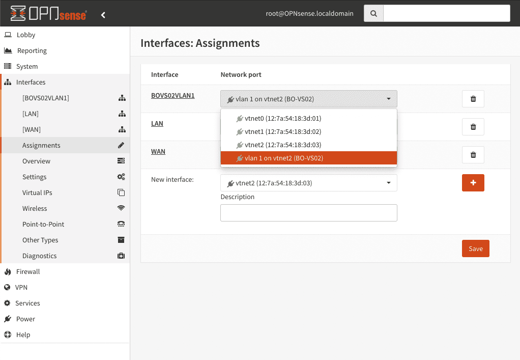
2. now we assign the VLAN to the interface
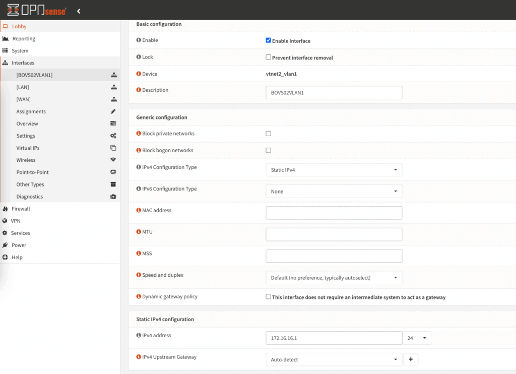
3. the interface is activated and defined
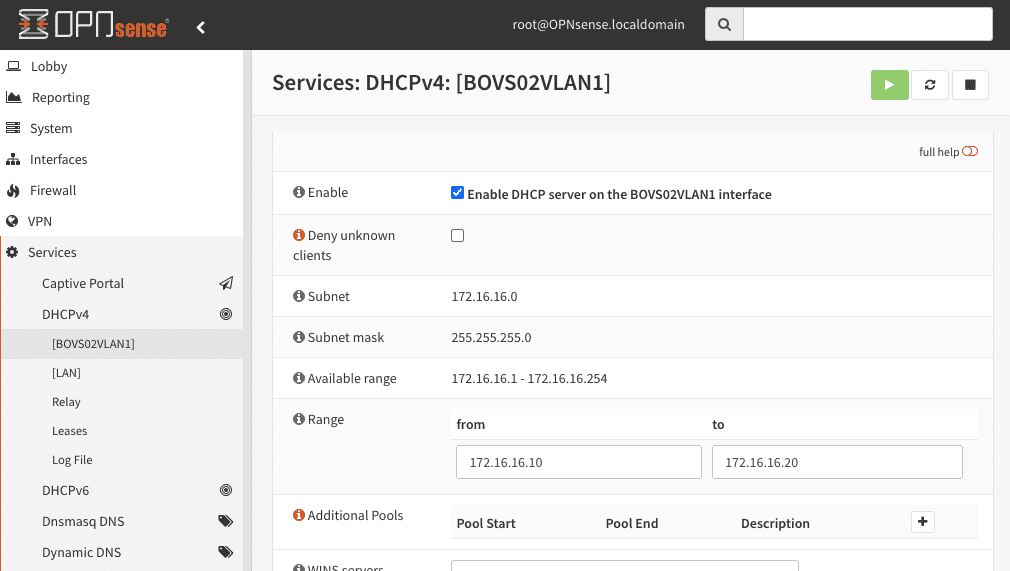
The last point is to configure and activate DHCP within the VLAN.
Step 4
Now all the necessary requirements have been met and we can start connecting servers to the firewall.
For our example, we will switch to the Cloud Panel where the server to be connected is located. There you connect the server to the Virtual Switch (placed there by step 1).

Step 5
To check, we now see if the server just connected to the VS02 has been assigned an IP address from the previously defined DHCP pool. To do this, we open the server’s VNS and enter the corresponding command (in our case, for example, “ip a”).
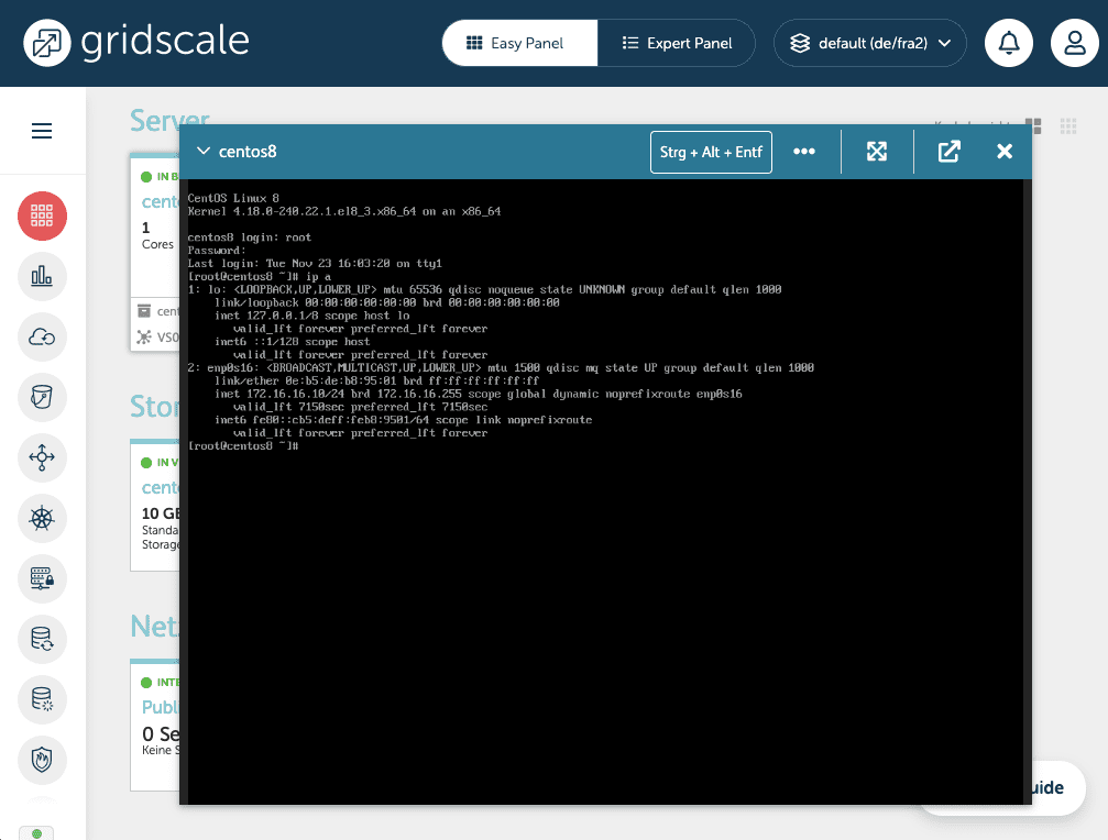
If one of the IP addresses from your DHCP pool appears in the shell, everything has worked.
Congratulations! You have connected a server to a firewall via a breakout. Now you can add more servers to this firewall.
Now you only have to define the rules that are important for you in the firewall.
Create additional VLANs
If more VLANs are needed, you can simply repeat the steps explained above. Create additional virtual switches in the Partner Panel and connect them to the breakout. Configure the interface and DHCP accordingly in your firewall. Then connect more servers to the virtual switch and define your firewall rules. Done.